VAGNOV

Blog

  • SEQUENTIAL CIRCUITS


    8.1 INTRODUCTION

    A sequential circuit consists of memory elements, such as flip-flops and combinational logic circuits Figure 8.1 shows the basic block diagram of a sequential circuit. The sequential circuit is a feedback system as the present state of the_ circuit is fad back to the input decoder and is used determine the next state of the machine.

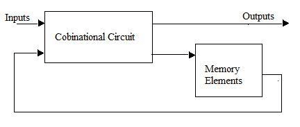
    Basic block diagram of sequential circuit 👆👆👆👆👆

    The next state of the LA Outputs machine can be determined by the present state of the circuit and inputs. The input decoder performs the logic operations based on the present state of the circuit and inputs and generates Basic block diagram of sequential circuit next state code of the circuit Then the next state code is stored in the memory, in sequential circuit, the output depends on the im- mediate input to the circuit and also the present state of the circuit. The present state of the circuit is also stored in the memory element.

    There are two types of sequential circuits, such as synchronous sequential circuit and asynchronous sequential circuit. In synchronous sequential circuit, state changes are synchronized to the periodic clock pulses, but state changes of asynchronous sequential circuit are not synchronized with clock signal. Most commonly used sequential circuits are registers and counters. In this chapter, operating principles and applications of registers and counters are discussed in-detail

    SEQUENTIAL CIRCUITS

    • REGISTER
    • SHIFT REGISTER
    • CLASSIFICATION OF SHIFT REGISTER
    • SERIAL IN-PARALLEL OUT (SIPO) SHIFT REGISTERS
    • SERIAL IN-SERIAL OUT(SISO) SHIFT REGISTERS
    • PARALLEL IN-SERIAL OUT (PISO) SHIFT REGISTERS
    • PARALLEL IN-PARALLEL OUT (PIPO) SHIFT REGISTERS
    • UNIDIRECTIONAL SHIFT REGISTERS
    • LEFT SHIFT REGISTERS
    • RIGHT SHIFT REGISTERS
    • BI-DIRECTIONAL SHIFT REGISTERS
    • SERIAL IN-PARALLEL OUT (SIPO) SHIFT REGISTERS = (a) – 4-bit sipo shift register using d flip-flop (b) – sipo shift register using j-k flip-flop
    • SERIAL IN -SERIAL OUT SHIFT REGISTERS
    • PARALLEL IN-PARALLELOUT SHIFT REGISTERS
    • PARALLEL IN-SERIAL OUT SHIFT REGISTER
    • BUFFER REGISTER
    • UNIVERSAL SHIFT REGISTER
    • UNIVARSAL SHIFT REGISTER USING MUX
    • APPLICATIONS OF SHIFT REGISTERS
    • TIME DELAY
    • SHIFT REGISTER COUNTERS
    • SERIAL DATA TO PARALLEL DATA CONVERSION
    • COUNTER
    • CLASSIFICATION OF COUNTER
    • ASYNCHORONOUS (RIPPLE) COUNTER = (a) 1 bit ripple counter (b) 2-bit ripple up counter (c) 2-bit ripple down counter (d) 3-bit ripple up counter (e) 3-bit ripple down counter (f) 4-bit ripple up counter (g) 4-bit ripple down counter
    • ASYNCHORONOUS DECADE COUNTERS

  • BI-M DIRECTIONAL SHIFT REGISTERS

    sometimes, the same shift register can be used as left shift or right shift with some additional circuits. we can multiply a binary number by 2 just simply placing the binary number in a shift register and shifting the number by one bit to the left. only care has to be taken that a ‘1’ is not shifted out of the most significant stage of the register. similarly, a binary number can be divided by ‘2’ when we simply shift the number to the right by one stage or one bit. the operation of bidirectional shift register can be explained using fig. 8.9. the bidirectional shift register is one in which the data can be shift either left or right. a three-bit bidirectional shift register using D flip-flop is shown in fig. 8.9 hare a set of NAND gets are used to select data input Frome the right or left adjacent flip-flop, as selected by the LEFT/RIGHT control line. the serial left shift and right shift operating and register can be performed by using LEFT/RIGHT control signal when the mode control signal LEFT/RIGHT=1 the data will be shift to the right when clock pulses are applied. in the mode control signal LEFT/RIGHT=0, the input data will be shifted to the left when clock pulses are applied. the mode control signal LEFT/RIGHT should be changed only when CLK=0, otherwise the data stored in the shift register may be changed.

  • SI UNITS

    In French, SI stands for “System ‘ international d’ units” and is the modern form of metric system. this system was finally agreed upon at the eleventh international conference of weights and measures, 1960. SI system possesses features that make it logically superior to any other system and also more convenient as it is coherent rational and comprehensive. a system of unit said to be coherent if the product or quotient of any two-unit quantities in the system is the unit of the resultant quantity without the introduction of any numerical factor. for example, unit velocity will result when unit length (distance) is divided by unit time; unit force will result when unit mass is multiplied by unit acceleration.

    this system of units is now being adopted throughout the world because of its logical superiority over other systems of units. India, by an act of parliament no. 89,1956, switched over to the metric system of weights and measures. the definition of various units given in the act conform to the definitions of the SI units.

    the international system of units is based on seven base units with a unit symbol assigned to each of them as given in Table-1                                                                                                                                                                            Table-1. Base Units

    SL NO.Physical quantityName of SI unitsymbolDimensional Notation.
    1.
    2.
    3.
    4.
    5.
    6.
    7.
    Length
    Mass
    Time
    Electric current
    Thermodynamic temperature
    Luminous intensity
    Amount of substance  
    Meter
    Kilogram
    Second
    Ampere
    Kelvin
    Candela
    Mole  
    M
    Kg
    S
    A
    K
    Cd
    mol
    [L]
    [M]
    [T]
    [I]
    [0]
    [J]
    [mol]

    Definitions Of The Base Units

    length: one meter is the length equal to 16 50 763. 73 wavelength in vacuum of the radiation corresponding to the transition between the levels

  • Hello world!

    Welcome to WordPress. This is your first post. Edit or delete it, then start writing!